How 3d Graphics Work
Matthew Kaney
This is an adaptation of a flyby I gave in September 2015. It gets into pretty great detail about how 3d graphics works, both in general, but also in the case of Three.js. You don't need to know everything here to make cool stuff with 3d graphics on the web, but the more you know, the easier of a time you'll have figuring out what's going on and how you can bend it to your will.
I think this is decent introduction to 3d graphics as a topic, but it's deliberately light on Three.js details. That's because a lot of these ideas are pretty universal—Three.js is just one implementation among many. However, if you're just here to learn that particular library, the best thing to do is just skip ahead to my code examples.
Part I: Where Do My Points Go?
In the beginning, a 3d scene is just a bunch of abstract geometry, and the simplest geometric object is the lowly point. Therefore, if we want to make anything in 3d, we're going to have to plot some points first. Now, there are three related terms that come into play, so let me clear things up:

Points
Points should look familiar to you if you've ever taken any geometry in school. A point is simply a set of numbers (two numbers for 2D, three for 3D, etc) that define a specific, infinitely small location in space. We divide up space into some sort of coordinate system, which allows us to assign numbers to locations. In this example, the point is at location x=1 and y=2, so we call this point (1, 2).

Vectors
A vector is also a set of two (or three, etc.) numbers. Unlike points, however, a vector represents a specific path through space. In this example, the vector (1, 2) means "move one unit in the positive x-direction and two units in the positive y-direction", or more simply, "go right one and up two".

A vector is just an instruction for moving through space, so it doesn't matter where you start from. All that a vector tells you is a direction to point and a distance (or magnitude) to travel in that direction. That means that because all these vectors have the same direction and distance, they are the same...

...while all of these vectors are different.

As you can see, vectors and points are basically identical types of objects with subtly different meanings. Because they're so similar, most libraries (Three.js, and also P5.js/Processing) use one vector object to represent both points and vectors. This also makes sense in terms of the math, because the vector (1, 2) will lead you to the point (1, 2), assuming you start at the origin. For now, we'll make this assumption and use the Three.js Vector object for our points (but keep in mind, that a vectors can actually start from any point).

Vertices
Another term that you'll encounter is vertex. A vertex is a special name for a point that forms part of a larger shape. In 3d graphics, we don't want to just plot points, we want to connect them into larger 3d models, so vertices are what we need.
With this in mind, we can start plotting these points. At this point, we now have a big question to answer—where do these points go? In answering this question, we'll step through five essential objects every Three.js project will need.
Our First Object: Geometry
So, where are these points stored? In Three.js, they go in a Geometry object. The Geometry object contains an array of vertices, and then an array of faces, that connect our vertices with triangles.
If you wanted, you could construct this geometry manually. So, to create the triangle on the right, you'd use this code:
var myGeo = new THREE.Geometry();

myGeo.vertices[0] = new THREE.Vector3(0, 0, 0);
myGeo.vertices[1] = new THREE.Vector3(2, 0, 0);
myGeo.vertices[2] = new THREE.Vector3(0, 3, 0);

myGeo.faces[0] = new THREE.Face3(0, 1, 2);
The arguments for Vector3 are three floating point values for the X, Y, and Z components of the vector. These can be any real number, positive or negative. So, you'll see that the first vertex we define is at the origin, the second is off to the right, and the third is up above.
The arguments for the Face3 object is the index of the vertex that you wish to connect. So, we're telling the face here, "draw a triangle from vertex 0, through vertex 1, to vertex 2". It's very connect the dots.
Because we're referring to vertices by index, we can use vertices multiple times, like in this rectangle:
var myGeo = new THREE.Geometry();

myGeo.vertices[0] = new THREE.Vector3(0, 0, 0);
myGeo.vertices[1] = new THREE.Vector3(2, 0, 0);
myGeo.vertices[2] = new THREE.Vector3(0, 3, 0);
myGeo.vertices[3] = new THREE.Vector3(2, 3, 0);

myGeo.faces[0] = new THREE.Face3(0, 1, 2);
myGeo.faces[1] = new THREE.Face3(1, 3, 2);
Notice that we refer to the indices with "1, 3, 2" instead of "1, 2, 3". We do this because, as it turns out, the order doesn't matter here, except that you have to specify the vertices in going counterclockwise. Vertex 1 is bottom right, 3 is top right, and 2 is top left, so we could have written "1, 3, 2", "3, 2, 1", or "2, 1, 3". All would work the same.

And what about "1, 2, 3"? You could do that, but then you'd be looking at the back of your face, because when you look at it from behind, the order of the points is counterclockwise again. All faces have a front and back side. What the back side looks like is up to the system—in Three.js, the back side of a face is invisible by default. If you have geometry that's not always showing up, it could just be that the faces are facing away from you.
This seems tedious. Do I need to know this?
No. I mean, the more you understand about how this stuff works, the better equipped you'll be to figure out weird things that happen. But, we wouldn't get very far if every 3d object involved writing hundreds of lines of vector-placing code. Because of this, there are better ways to make geometry. The first way is using a geometric primitive. Three.js has several built-in specialty Geometry objects, like so:
var myGeometry = THREE.BoxGeometry(1, 2, 1); // width, height, and depth

// or...

myGeometry = THREE.SphereGeometry(3, 20, 20); // First is the radius, second and
                                              // third controls how smooth it is
The second method is to store this information in an external model file. For example, if you look at the old, but very common OBJ file format, you'll see that it's very similar to the code we wrote above. Three.js uses a special JSON-based 3d object format. There are various exporters and converters to help you integrate Three.js into an existing workflow. To import a JSON file, do this:
var loader = new THREE.JSONLoader();
loader.load( "my_model.js", function( geometry, materials ) {
  // This gives us a geometry object and an array of
  // materials that affect how the object looks.

  // Do something like this to add it to your scene
  var myMesh = new THREE.Mesh(geometry, materials[0]);
  myScene.add(myMesh);
});
Our Second Object: Mesh

As discussed earlier, the simplest 3d object is a geometry object, which is a collection of vertices in space, as well as faces to connect them all. (There are some other things that can be stored in the Geometry object, but we'll come back to that).

That's not enough, though! To turn our geometry into a fully-fledged 3d object, we need to combine that geometry with a description of that the object looks like (a Material object), as well as a transformation to allow us to better control the position and orientation of the object in space. Three.js wraps up all of these into an object called a Mesh.
The transformation object allows you to move, rotate, and scale your whole object. Under the hood, the tranformation is an object that takes a point and then outputs a different point based on where that point would move to after the model undergoes various transformations. The math behind this is pretty interesting, but we don't actually need to cover it here. Just know that meshes can be transformed in different ways.
The code to do all of this is very straightforward: create a geometry object, create a material object, and then create a mesh that combines them. (Note: If you want several copies of an object, you'll need to create multiple meshes, but they can all share the same Geometry object—they definitely should, to save space.)
var myGeometry = new THREE.SphereGeometry(1,20,20);
var myMaterial = new THREE.MeshBasicMaterial({ color: 0x4BBBEB });

var myMesh = new THREE.Mesh(myGeometry, myMaterial);
Now, because the Mesh object has a built-in transformation matrix, you can control its position, rotation and scale very simply:
myMesh.position.x = 5.5;
myMesh.position.y = 10.5;

myMesh.rotation.y = 0.5; // This is in radians, by the way

// You can also use the set function to set the x, y, and z components in one go
myMesh.scale.set(3, 3, 3);
Our Second-and-a-Half Object: Object3D

In Three.js, the Mesh object is actually a special case of a general object, the Object3D object. This object contains children (added using the add() method), and has a built-in transformation that is applied to all of them. If we want to apply another layer of transformation to our mesh, we can wrap it in an Object3D...

...and then we can wrap that Object3D in another object, or wrap multiple objects together into the same Object3D—really any combination. Other 3d graphics systems may call these "Groups" or "Null Objects" or something else, but the principle is the same. Strictly speaking, these intermediate objects are optional (that's why they're "second-and-a-half"), but they're essential if you want complex systems of movement.
Our Third Object: Scene

At the top of the hierarchy, everything needs to be wrapped up in a Scene object. Like everything before it, Scene has its own built-in transformation and an add() method for adding children. The scene is ultimately what gets passed to the renderer, so if you want an object to be visible, it has to be added to a scene at some point.
The code for this is pretty simple straightforward. The key is the add() method
for adding children to containers:
var myMesh = new THREE.Mesh(myGeometry, myMaterial);

var myContainer = new THREE.Object3D();
myContainer.add(myMesh);

// You can then modify the tranformations of a container
myContainer.rotation.y = 0.5;

//And then add the container to the scene
myScene.add(myContainer);
Two notes on transformations:

As you can see, a lot of 3d graphics involves stacking transformations. Two things about transformations bear discussing here: First, because of the way that math works, several transformations can be pre-combined into a single transformation. This means that you can go wild creating hierarchies of transformations, knowing that the system can compute the result very quickly.

Secondly, every transformation is applied relative to the origin point. This means that order matters. As you can see in the diagram, applying the same two transformations in different orders results in a different final object.
So, where are we again?
First, we wanted to know where our points went. So, then we assigned our points specific locations in space and then sent them through a journey of transformations to arrive at a final destination. Question answered, right?
Well...
The problem, of course, is that these points don't really exist in 3d space. The points in the lovely "rotating cube" to the right are actually moving in a vague oval shape along the very flat surface of your screen. Ceci n'est pas 3d.
Our Fourth Object: Camera

To actually turn these abstract points into real pixel locations on your screen, we'll need another object—the camera. It's often helpful to think of 3d cameras as similar to real-world cameras, but ultimately, they're just made up of two more transformation matrices.

The first tranformation, the view transform, works basically the same as the transforms we've seen thus far. It just moves the camera into position (or, if we're being technical, it moves everything in the world to the front of the camera.)
The second transformation, the projection transform is a different sort of beast. It takes a point in 3d space and converts it to a 2d point on your screen in pixels along with an optional z-value corresponding to the depth at that pixel. There are two popular types of projections in 3d space, represented by two separate camera objects in Three.js.

The first, orthographic projection, is the simplest. For this, you just discard the depth data in your scene, taking a rectangular area of space and smashing it onto a flat plane. This means that objects that are the same size look the same size in your final image, no matter how close or far they are. In Three.js, an orthographic camera is specified by six values: the top, bottom, left and right edges of the projected image, as well as the nearest and farthest distances that will be rendered. These values are all relative to an imaginary viewer, and everything that falls outside the space they define isn't rendered. In code, that looks something like this:
var left = -3;
var right = 3;
var top = 5;
var bottom = -5;
var near = 0;
var far = 5;

var camera = new THREE.OrthographicCamera(left, right, top, bottom, near, far);
Now, orthographic cameras are great if you're making architectural drawings, or if you want a cool effect for your indy game. But, they're not terribly realistic. That's where the other type of projection comes in.

The second type, perspective projection, is much closer to how we actually see the world. A perspective camera carves out a space that gets larger the farther away it goes, meaning that, when this space gets compressed onto a single plane, the objects further away become smaller. Three.js also has a perspective camera, which takes four arguments: the aspect ratio of the final image, the field of view (that is, the angle in degrees between the top and bottom planes of the viewing area), as well as the nearest and farthest distances again. Changing the field of view changes how dramatic the perspective effect looks, and is similar to changing the focal length on a physical camera. The code often looks something like this:
var aspect = window.innerWidth / window.innerHeight;
var fov = 45; // This is nice medium field of view
var near = 1;
var far = 20;

var camera = new THREE.PerspectiveCamera(fov, aspect, near, far);
Again, the math behind how this works is pretty interesting, but totally outside the scope of what I want to explain right now (also, I don't fully understand it either).
 Credit: Astrofra / Wikimedia Commons / CC-BY-SA-4.0
Now, when we make our 2d image, where does our depth data go? We can store this data in a second image called a z-buffer that maps grayscale values to the closeness or farness of the pixels in our scene. If you've ever worked with the depth camera on a Kinect, this should be familiar.
Our Fifth (and Final) Object: Renderer

If you've been keeping track, in step 3 we wrapped up all of our 3d objects in a giant Scene object. Then, in step 4 we added a camera so we have a viewpoint onto our scene. Finally, we must create a Renderer object that takes our scene, looks at it through our camera, and renders result to the screen. To create a Renderer, do this:
var renderer = new THREE.WebGLRenderer();
renderer.setSize( window.innerWidth, window.innerHeight );
renderer.setClearColor( 0xffffff ); // Set background color

// Now, attach the actual renderer HTML element to the HTML of our page
document.getElementById("container").appendChild( renderer.domElement );
Then, whenever you need to render a new frame, you simply call:
renderer.render(myScene, myCamera); // Magic
Such a simple function to do so much. But what is it doing? Well, if you must know, it first applies all of those transformations that we've been accumulating, converting all our points to 2d screen coordinates. Then, it does some cleanup, specifically:
- Getting rid of triangles facing away from us (remember when we talked about back faces?)
- Using the z-buffer to determine what faces are in front of other faces. Get rid of anything that's covered up.
- Getting rid of anything that falls outsided of the camera's viewing area.

Having done all of that, then the renderer performs the process of rasterization, where our vector shapes are converted into an array of individual pixel values. Finally, our 3d points have come to rest in the grid of pixels that is our screen. We know exactly where our points are, but now this raises a second big question...
Part II: What Color Are My Pixels?
For all of the examples so far, the answer has been "blue", which is a great answer, but not very complex. Actually, the answer is very subjective and unlike the question of how to get 3d points onto a 2d screen, there's not really a "right" answer here. Usually, the answer will be a combination of the color of an object, as well as various other factors that describe how the object responds to light, shadow, fog and other effects. In Three.js all of this is wrapped up in the Material object. There are lots of different possibilities, so I'm just going to discuss a couple of basic factors here.
How we can describe our model's appearance
If you recall, a Mesh is made of a material and a geometry object. So, this gives us two ways to store information about the appearance of our meshes.
- Per Material - Affects the entire model
- Per Vertex - Affects only individual vertices
To begin, we can see how this works with color. You've already seen one type of material,
the THREE.MeshBasicMaterial. This allows you to specify a color for the entire
material, with no additional lighting or anything else. So, if you specify a blue
color for the model, that's the color of every pixel in that model.
On the other hand, we can also assign a color to each vertex (in this case, red, green and blue). Once we do that, then the renderer automatically creates a gradient between our three points. For most material properties, we'll want a combination of properties that apply to everything and properties that are specified per vertex and automatically interpolated. We'll see how this works by examining two cases—lighting and texturing.
Lighting
The most popular material effects in 3d graphics is lighting. In the real world, the interaction of light bouncing around a scene is fiendishly complicated, so 3d graphics (especially graphics that need to update in real time) cuts some corners. Three.js supports two popular approaches to doing 3d lighting, each with its own type of Material object.

The first, Lambert reflection, calculates the brightness at a point based on two vectors, the light vector (that is, the direction from the surface to any lights) and the normal vector, or the vector perpendicular to the surface. The algorithm basically states that the closer the two vectors are in direction, brighter the surface is.
In Three.js, you can create this by creating a THREE.MeshLambertMaterial
object and attaching it to your mesh.

The light vector is pretty straightforward. Three.js (and most graphics systems) supports several different light shapes, each of which sends out light in different directions. For example, with a directional light, the light vector is going to be the same for all surfaces, no matter where the surface is in space.

The normal vector is also pretty simple—it just points outward from the model. However, if we tweak the normal vector's direction, we can control different aspects of the object's lighting. For example, at the right is a basic pyramid. It has four faces, each with a normal pointing in a different direction.

Remember, though, that we can't describe how a material behaves per face. We have to do it per vertex. So, we can say that each vertex needs to have three separate normals, depending on which face that vertex is a part of. We copy the normals from our faces, and get the same effect.
In Three.js you can specify that a material has flat shading by adding the
shading: THREE.FlatShading parameter to our material. It looks like this:

But what if we pick some other direction for our vertex normals? What if we take our three normals and average them? When we do that, then we get another gradient across the face, this time a gradient of directions. And, the end result is that our object now looks like it's much smoother than before.
In Three.js this is specified by shading: THREE.SmoothShading, which
is the default. Applying this setting to our same sphere gives us this:
Notice that the surface is very smooth but the silhouette is still weird and bumpy. We haven't actually added more geometry, we've just told the lighting engine to pretend that our surface is smooth.

The second type of lighting is Phong reflection. This is an improvement on Lambert Shading that takes three vectors, the light direction, the normal vector, and the vector from the surface to the viewer.
The normal and lighting vector work the same as in Lambert reflection—more direct light makes the surface appear brighter—but Phong reflection also compares the direction to the viewer with the direction that light would bounce off the surface. If the two are similar, then the surface is even brighter, like how a shiny surface has very bright highlights when you catch it at the right angle.
In Three.js, you can create this by creating a THREE.MeshPhongMaterial
object and attaching it to your mesh. This material has a "shininess" property that
determines how harsh these highlights are.
Here's an example of the two lighting models, Lambert on the left and Phong on the right. They're basically the same, except that the Phong example has a highlight when the light is behind the cube.
Textures

This is great for single-color objects, but basically nothing in the real world actually looks like that. If we want the amount of detail of the real world, we're going to need images of real-world textures. Unfortunately, images are two-dimensional, and we need a way to wrap them around our 3d models. As centuries of mapmakers have discovered, this can be a difficult and controversial undertaking. There's no way to fully automate this process, so we just have to do it by hand.

To start, create a brand-new coordinate grid for your texture. It's common to label the axes "U" and "V", because, well, X, Y and Z are already taken. For simplicity's sake, the bottom corner of the image is (0, 0) and the upper-left corner is (1, 1), regardless of how big the actual image file is.

Now, for every point in your 3d space, you specify a second, alternate point in the texture space. These UV coordinates also get stored in your geometry and get referenced whenever a material wants to map an image to your model. Keep in mind, although the two points are linked, you can move one without moving the other. This sort of mapping is something that you'd probably do in a 3d modeling program, and there's a certain art to making the best use of your texture space.
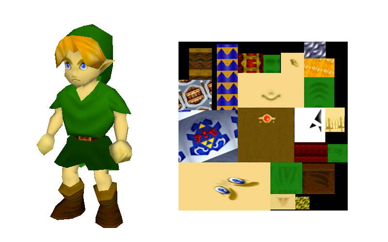
When done correctly, the computer will have everything it needs to know in order to take a collage of different textures and correctly paste the right images on the right parts of the model.
Once you've set up a UV mapping, you can import an image and then set it as a model's texture map with code like this:
var myGeometry = new THREE.SphereGeometry(1,30,30);
var myTexture = THREE.ImageUtils.loadTexture("tex/noise.png");
var myMaterial = new THREE.MeshPhongMaterial({ map: myTex });
var myMesh = new THREE.Mesh(myGeometry, myMaterial);

scene.add(myMesh);
One last thing about textures: they don't need to be used for getting color information onto a model. They can be used to encode any parameter that should vary over the surface of the texture. On the left above, you can see what happens when the image is used as a simple texture map. On the right, you can see how the same image looks when applied as a bump map. The bump map uses the image data to change the surface normal which, if you read the previous lighting section, affects the brightness of the image. In addition to bumpiness, Three.js also supports using textures to control the shininess and opacity of a model.
Conclusion
That was a lot to get through
I know. I'm sorry. But you did it!
So, what's next?
Well, if you're still in a learning kind of mood, one of the next steps is the wild world of shaders. A shader is a special kind of program that runs on the graphics card and actually does the rendering. There are two types of shaders, which not coincidentally correspond to the two parts of this essay. The vertex shader is run once for each vertex in your world and answers the question of where the vertex needs to go. And the fragment shader is run once for every pixel in the final render and answers the question of what color that pixel needs to be.
What I've described so far is basically how the built-in shaders in Three.js do things (which happens to generally be the most common ways that these things are done). But there's no reason that your graphics have to follow any of these rules. If you've got some wild dream for what 3d graphics should do, why not write it yourself?
But, do you have some code for me?
Yes. I made a couple projects that are simple and have well-documented source code.
This template does nothing, but it includes all the different components that your Three.js project must have. Whenever you look at other projects, see if you can spot all of these pieces.
This template creates a simple model of the sun, earth, and moon. It uses a texture, a light, several different materials, and a lot of nested transformations.